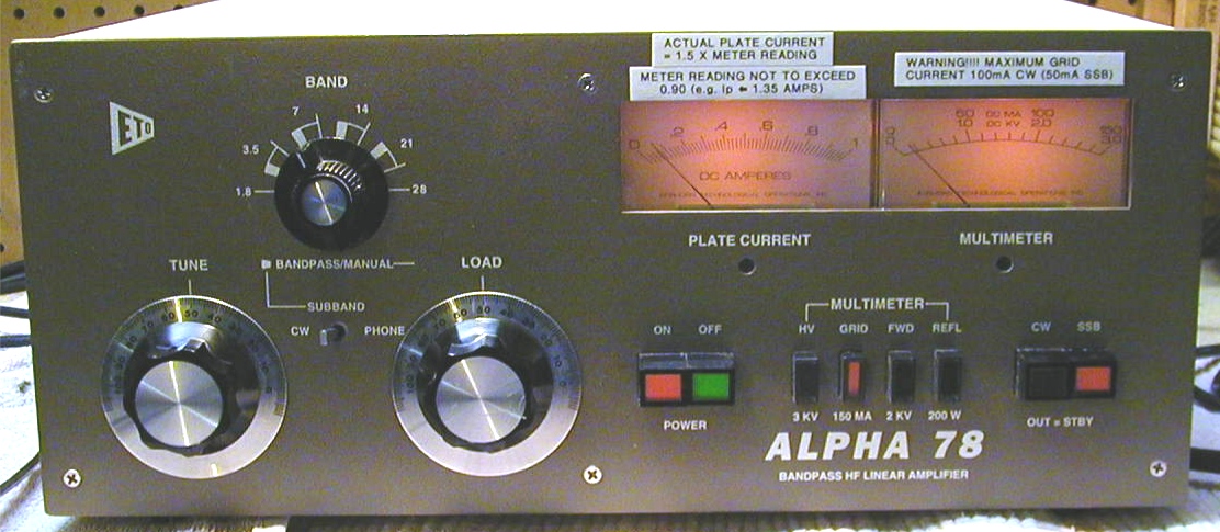
The ETO Alpha 78 HF Linear
Amplifier is an excellent choice for folks who are looking
for an economical way to get legal limit "no-tune" capability in an HF linear
amplifier.
There are, however, several minor shortcomings in this amplifier that potential buyers
should be aware of. I believe these problems are mainly the result of the regulatory
framework that existed at the time Alpha 78 was designed. Fortunately, however, these
problems are easily corrected.
Plate Current Meter Rescaling
The ETO Alpha 78 was designed
at a time when the US Federal Communications
Commision (FCC) part 97 rules for Amateur Radio Service RF power were specified
in terms of maximum allowable plate input power. At that time the regulatory limits were
1 KW maximum DC plate input power on CW and 2 KW maximum peak envelope
power (PEP) on SSB. At 60% efficiency, this corresponds to 600 watts output on CW
and 1200 watts PEP output on SSB. At these levels, the anode current in the Alpha 78
would be approximately 714mA for CW (low voltage setting) and 950mA peak for SSB,
respectively and plate dissipation would be a very conservative 400 watts on CW and
800 watts PEP on SSB. Under these operating conditions, the Alpha 78 works just fine.
The current FCC part 97 rules for Amateur Radio Service RF power which specify
1500 watts maximum output power are a different story, however.
While the tubes and the power
supply in the Alpha 78 are up to the job of delivering
1500 watts of CW RF output power, there are a couple of other problems that crop up
at this level. At 1500 watts RF output and 60% efficiency (typical for the Alpha 78), the
anode current runs around 1.2 amps. Since the plate current meter in the Alpha 78 has a
full scale range of only 1.0 amps, it will usually end up being pegged when running the
amp
at 1500 watts CW output. Once the meter is pegged, you lose a lot of information. This
makes it difficult to properly adjust the tuning on the amp.The obvious fix for this is to
rescale the meter to allow for the maximum expected anode current. Rescaling the meter
for a maximum value of 1.5 amps provides sufficient scale range for worst case
conditions
(~3.2 KW input power). You can do this by adding an external shunt across the Alpha 78
plate current meter. The resistance of the Alpha 78's internal meter shunt is 0.063 ohms.
Placing a 0.125 ohm external shunt across the meter terminals will change the full scale
value of the meter from 1.0 amps to 1.5 amps. I used a pair of 0.250 ohm x 1 watt x 1%
silicone coated wirewound resistors in parallel for my rescaling shunt (Huntington
Electric
ALSR-1; Digi-Key P/N ALSR-1-.25-1%). You can mount the resistors across the meters
stud terminals which are accessible if you remove the power supply board that bolts to
the filter capacitors (see figure 1). Just so there is no confusion about the meter
reading
after resclaing, I put a P-Touch label above the plate meter which indicates the new scale
factor (see figure 2).
Figure 1 -
Plate Current Meter Rescaling Shunt Installed in the Alpha
78 Power Supply
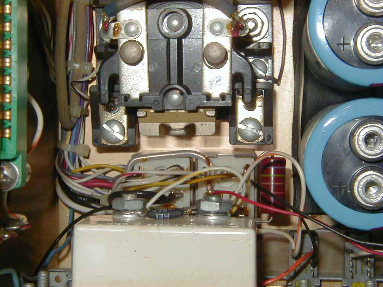
Figure 2 - P-Touch Labels on the Alpha 78
Indicate Plate Current
Meter Scale Factor and Maximum Limits
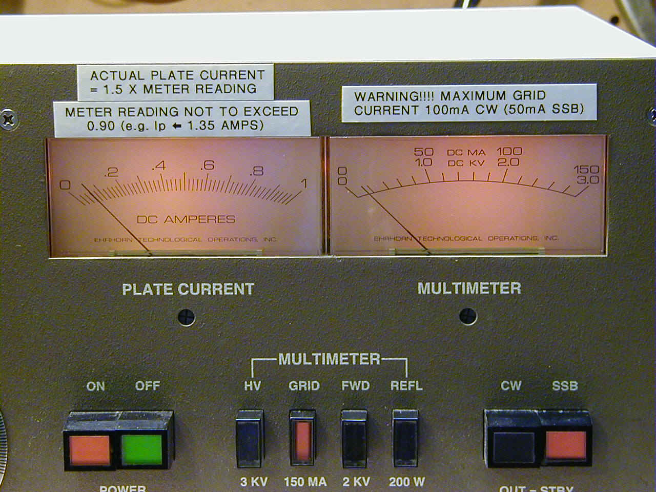
Plate Overcurrent Shunt Resistor
The second problem with Alpha
78 has to do with the sizing of the anode overcurrent
sense resistor R111. In the stock Alpha 78, this is a 25 ohm x 25 watt wirewound which
worked fine under the old FCC part 97 input power limits. At 710 mA maximum CW
anode current, this resistor only dissipates 13 watts. In SSB service, peak dissipation
reaches close to 25 watts, but the duty cycle is low enough that average dissipation
is much lower. Under the current FCC rules that allow for 1500 watts maximum CW
output power, this resistor can run much hotter. For example, under the current rules,
you could run the amplifier at 1500 watts x 0.55% plate efficiency in RTTY service
and
still not exceed the maximum plate dissipation of the three 8874's. At this level,
however,
the steady state DC anode current be 1.3 amps. While this seems to be no problem for
the power supply, it is a problem for R111 which dissipates 42 watts at that level
of
anode current. Interestingly enough, I discovered this problem quite by accident when
servicing the Alpha 78's at our local club station. In both these amplifiers the area of
the
G-10 printed wiring board (PWB) underneath R111 was charred indicating that the
the resistor was running very hot. In the case of one amplifier, almost all of the epoxy
resin in the G-10 substrate had been cooked out of the laminate leaving only the
fiberglass cloth and some carbon residue behind. This problem is probably exacerbated
by the meter scaling issue. As far as I know, the two Alpha 78's at our club were never
used in RTTY service, rather they were used almost exclusively for high duty cycle CW
and SSB contesting. Even under these conditions R111 might have been up to the task
because of the < 50% duty cycle associated with this kind of operation. Unfortunately,
without the rescaled plate current meter that doesn't peg before you reach full output it
is
really difficult to tune the amplifier properly. Since the meter was pegging, I suspect
that
operators at our club were probably tuning the amplifier for maximum output power
without paying much attention to peak input power or anode current. In any case, to fix
this problem, I decided to replace the stock 25 watts resistor with a 50 watt part. After
looking around for parts that would fit on the power supply board, I decided the best
thing
to do would be to parallel two 25 watt x 50 ohm resistors that had the same form factor
as the stock R111 resistor (Ohmite 50 ohm x 25 watt vitreous enamel adjustable power
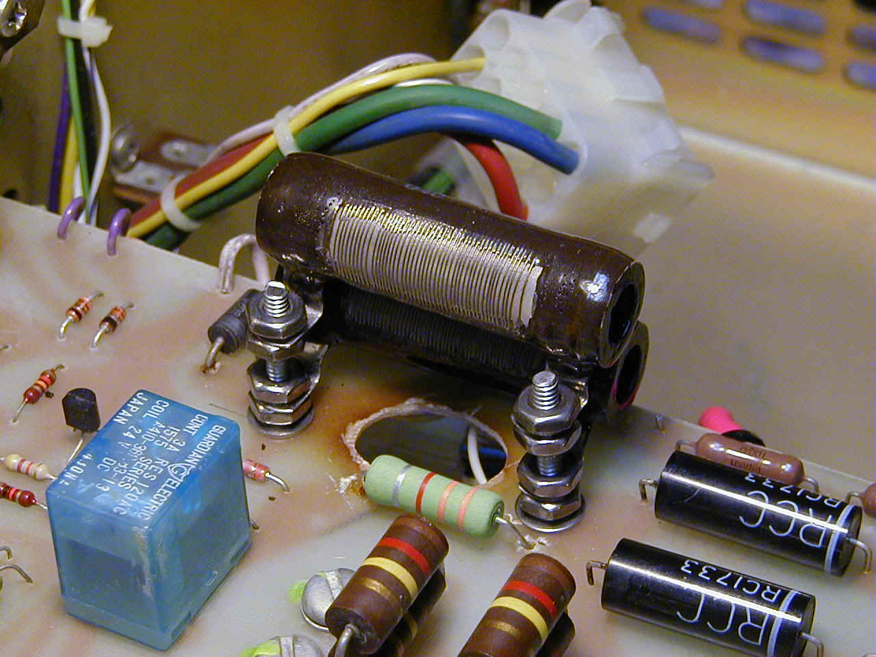
resistor; Digi-Key p/n D25K50R-ND). The stock resistor is stud mounted, so I
paralleled
the new resistors by stacking them vertically on 6-32 x 1" machine screws (see figure
3).
The hole in the PC board that is visible in the photo was the burnt underneath the stock
R111 resistor that I cutout (there are no PCB traces under this part). This hole in the
board
should provide the added benefit of a little extra ventilation around R111.
Figure 3 - Paralleled 50 ohm x 25 watt
Vitreous Enamel Wirewound
Resistors Installed in Place of Alpha 78 Stock R111 Sense Resistor
Preset Tuning Cover
A useful tool for safely adjusting the bandpass presets on the
Alpha 78 is to fabricate a
sheetmetal cover with an access cutout for the bandpass preset tuning capacitors (see
figure 4). Originally I thought about just drilling holes in the amplifiers stock cover,
but then
I decided that I didn't trust that my limited machining skills would produce a
esthetically
pleasing result (and it is very hard to put metal back once you have started cutting or
drilling). I had some thin gauge galvanized sheet metal laying around, so instead of
mucking
up the stock cover, I bent up a quick and dirty temporary tuning cover. Since it didn't
have
to look good or fit perfectly, it was very easy to fabricate. I just used blocks of wood
and
some C-clamps as as bending brake. Originally I just cut a rectangular opening in the
metal
over side that covers the preset tuning caps. Later on, I opened a second hole over
the tank
components when I needed to troubleshoot an arcing problem in the bandpass tuning section.
At first I was a little worried that the hole over the tank components would effect the
tuning,
so I did some A/B tests using a piece of aluminum to cover the hole. As it turns out the
effect of the hole on the amplifier tuning is negligible.
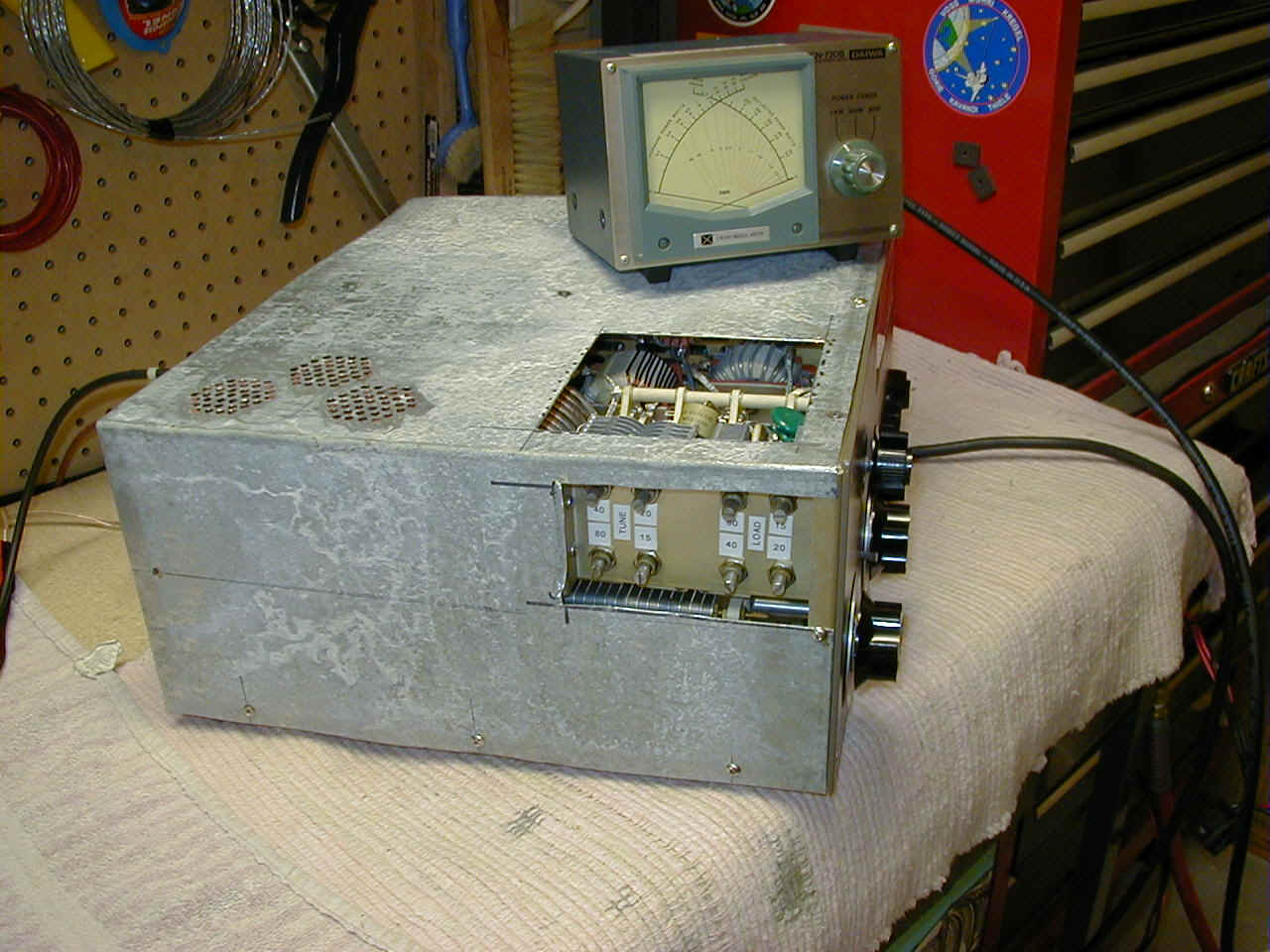
Figure 4 - Temporary Chassis Cover for Alpha
78 with Cutouts for
Adjustment of Bandpass Tuning Preset Capacitors and Tank Circuit
Access.
WARC Coverage
For those of you who want that extra 3dB of legal power that
you can't get with your 100
watt exciter on 30 meters, the Alpha 78 works just fine. In fact, it will do 1500 watts
output
(into a dummy load of course). Just set bandswitch to 7 MHz and use the manually tuning
mode. For 17 meters, operation appears to be possible using the 21 MHz manual tuning
mode. On the unit I tested, after careful adjusment I was able to get out around 1100
watts using ~50 watts of drive. Efficiency was a bit low, however, (only 50%), so I was
hesitant to push the amplifier any harder on this band. In the case of 12 meters there is
a
plate choke series resonance at 25.1 MHz (at least on the unit I tested), so I DO NOT
recommend using the Alpha 78 AT ALL for 12 meter operation as this is just asking
for
trouble.
If you have other suggested modifications or operating hints
for the Alpha 78, please let me
know and I will try to put them up on this page.
73 de Mike, W4EF....................................................................